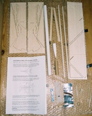
Parts list:
The VMX-2 Spaceplane is a new rocket glider kit by the equally new UK rocketry company, Orbital Engineering. You may have seen the pre-production prototype of this kit flying at various rocketry events in 2002, including the IRW and K-Lob. On opening the sturdy corrugated cardboard box, first impressions are very good. Three sheets and four strips of balsa wrapped in bubble wrap, a nice piece of BT-20, all the small parts in a resealable bag, and a very comprehensive looking set of instructions. I should point out at this stage that the kit supplied was a production prototype, and the final production kits may differ slightly.
|
Parts list: |
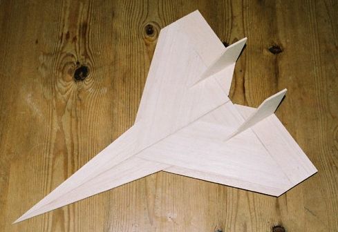
The first step is to free the wing parts from the balsa sheets and assemble them. The wing parts appear to have been partially pre cut by some sort of router. There are just a few tabs on each component which require cutting to free the part. I found it best to do a "rough cut" first, some way up the tab, to free the part. Then, once free of the sheet I did a "close cut" to remove the remains of the tab. It’s best to do this final cut from both sides of the part. The instructions indicate that either medium CA or light wood glue may be used for construction. I wasn’t in any rush (waiting for the glue to dry gave me the opportunity to write this review) so used EVO-STIK wood adhesive and "double glue joints".
I found the wing assembly straight forward with the exception of adding the leading edges. Although the positioning of these is quite clear in the wing plan diagram, there’s another diagram that I just found confusing. I couldn’t figure out what it was trying to show me, or even be sure what view it represented. Suffice to say that if you assemble the wings bottom side down, the leading edges go flat side down too! The wings must be assembled with a dihedral. I found this quite tricky and, once dry, had to fill a small gap at the aft end.
The next step is to add the elevons. These are attached to the aft end of the wings using mylar hinges. You have to make slots in the aft edge of the main wing and the forward edge of the elevon. I thought this was going to be a bit tricky, but as long as you keep the knife horizontal with respect to the wing/elevon, it’s not too bad. The positioning of the hinges seemed a bit odd, so I made mine equidistant along the elevon (which was a mistake, the manufacturer informs me that the unequal spacing is intentional). The hinges are attached by pushing a pin through the fins with the mylar tabs in position. Then CA is wicked into the resulting hole. This hinge design is very clean and I like it a lot.
 |
The fins are added to the elevons next, and this was where I had my first real trouble. Either the slots are too narrow, or the balsa the fins are cut from is too thick. I fixed this by scoring across the fin at the top of the tab, and then carefully paring away part of the tab thickness. The under wing strakes had to be modified in the same way. Once the fins and strakes are in place, the elevons are attached to the wing with the hinges, in the same way as the hinges were attached to the elevons.
The kit can be made into two slightly different versions, one for sport, the other for competition. The difference is in the arrangements made for the venting of unwanted ejection gases. In the sport model the gases are vented through a hatch in the top of the body tube. There are also parts to deflect the gases and strengthen the body tube interior. For the competition model, these parts are omitted and instead the motor most be plugged forcing the ejection gases out of the motor nozzle. I decided to build the sport model.
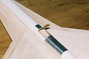 |
For the sport model the next stage is to cut out the vent hatch. This is best done with a sharp knife. A section must be left uncut to provide a hinge. This hinge is reinforced by the addition of a self adhesive foil strip. Enough of this foil is supplied to add protection to the body tube just aft of the vent. A cylindrical section of balsa is glued into place inside of the body tube just forward of the vent to deflect the ejection gases through the vent. Finally, a length of thick cardboard tube is fitted inside the body tube to strengthen it. This buts up to the balsa deflector. The aft end of this strengthener acts as the motor thrust ring. (For the competition model, an ordinary thrust ring is provided.)
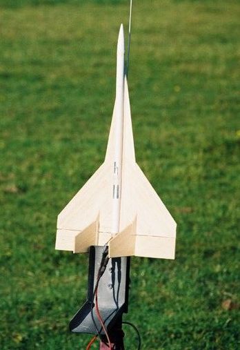
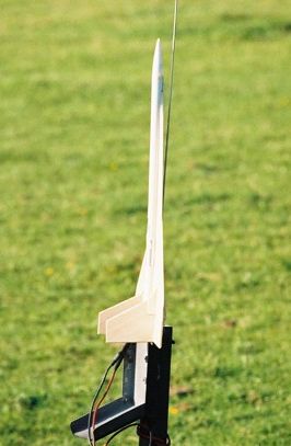
Next the body is attached to the wings. You need to take care here as it’s all to easy to not get the tube properly aligned. The triangular body fillets complete the main assembly. These must be trimmed square at the aft end and glued into position. Once dry the front end must be trimmed to match the leading edge wing extensions. The nose weight is added to the nose cone, which is secured only with tape to facilitate the addition of more weight during trimming.
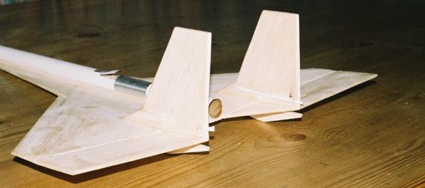 |
The mechanism to move the elevons is installed next. This comprises a pin pushed through the part of the fins mounted on each elevon, and two length of elastic attached to the part of the fins mounted on the wing. The pins pushed through the fins at 45° and secured using CA. Once dry the head of the pins is clipped off. The elastic is attached to the fins in the pre-made indentations (you did assemble them on the correct side, right?) and hooked onto the points of the pins. The tension can be adjusted by stretching the elastic more or less before hooking onto the pin points. You don’t need much tension. The instructions specify that the weight of a spent C6 motor should be just capable of lowering the elevon on to the strake.
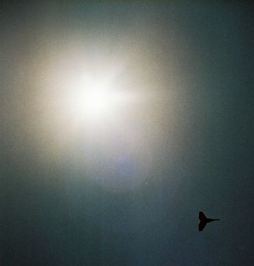
The way the mechanism works is that, at lift off, the airflow forces the elevons into the flat position. Once in normal flight however, the tension in the elastic is enough to overcome the airflow and raise the elevons for gliding flight.
It this point, the instructions suggest that you might like to radius the edges, but I think it's probably easier to do this as you go along, and that's what I did. Next, I gave all of the balsa areas a coat of sanding sealer, and then sanded smooth using progressively finer paper, until almost all of the sealer was removed. This may sound strange, but the idea is to fill the grain in the balsa, rather than add a nice shiny coating.
The instructions regarding trimming are quite clear. There are two main parts to it, the elevon tensioning covered previously, and sorting out the balance for gliding. This is done by test throwing the glider and adding small amounts of clay weight to the wings to correct for any roll or pitch. My first attempt at trimming, at UKRA 2003, led to the nosecone being pushed into the body tube. In retrospect, there was too much breeze. The small amount of damage was easily repaired.
 |
 |
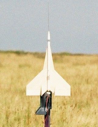
Flight #1
Location: Baildon Moor
Motor: B6
A perfect boost and translation to horizontal flight. Once flying horizontally, the glider made a 180° turn, then appeared to roll over, and slide sideways into what became a dive to the ground. The front body tube was crimped but easily repaired. The crimped sction of tube was excised and replaced with a new section, attached by means of a short coupler.
Before the next flight, I spent a lot more time at IRW 2003 trimming. There was a gentle breeze and I got it so it would glide really well either with, or against the breeze.
Flight #2
Location: IRW 2003
Motor: B6
Once again, a great boost and translation. Again it made a turn, but this time much wider. There was no roll, but the glider slowly pitched down and picked up speed. This was never corrected and it dived into the ground. Amazingly, there was no damage at all.
 |
 |
Flight #3
Location: IRW 2003
Motor: C6
Another great boost, but the flight was just a higher version of flight #2. What did I expect? This time there was a lot of damage. The body tube is folded up and the wings are broken across the span. It will be a big rebuild, which I haven't yet attempted.
I think the problem with the first flight was lack of trimming, that led to it rolling over and diving. For the second and third flights, I wonder if I had the elevons tensioned correctly? The tensioning is meant to be set such that the elevons are flat for the boost, and pop up for gliding flight. It might be that I didn't have quite enough tension. Therefore, as the glider pitched forwards, it picked up speed, and the increased wind speed forced the elevons into the horizontal position. Once that happened it would never be able to correct its attitude. I did follow the directions for tensioning, using the spent motor on the elevon, but maybe the exact position is critical? I passed on my thoughts to Orbital, but disappointingly, I never got a response.
This is an excellent kit. It's not exactly cheap, but the quality of the parts is second to none, the instructions are detailed and comprehensive, and even the packaging is first-rate. I really enjoyed building it. I must point out however that I can't recommend this kit for a beginner to rocket gliders. Despite the detailed direction, I never really had a successful flight. Since I've seen and read about many other successful flights of VMX-2s, I have to put that down to my own inexperience with rocket gliders which is limited to a couple of flights of an Estes Tomcat, and a few flights of an "AstronMike" style saucer glider. I reckon that either the trimming wasn't up to snuff, or that I didn't get the elevon tension correct. So in conclusion, this is a great kit, but if you're a beginner, practice your trimming on something cheaper first.
PostscriptThis article was first published, in two parts, in 10...9...8... the newsletter of the United Kingdom Rocketry Association. Between publication of the first part of this article and the second, I was informed by Verney Montague that BSMA have put up a handsome Gold Medal to be awarded to the first person to break the two minute barrier with a rocket powered Spaceplane. The medal has actually been around for 2-3 years. Anyone know if it's been won yet? |