 |
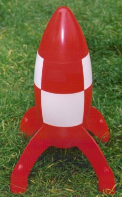
Tintinique
by Darren J Longhorn
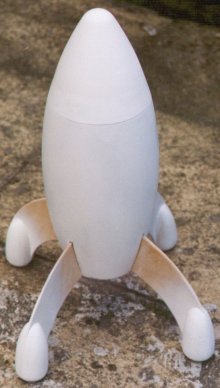
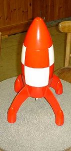
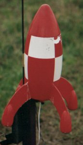
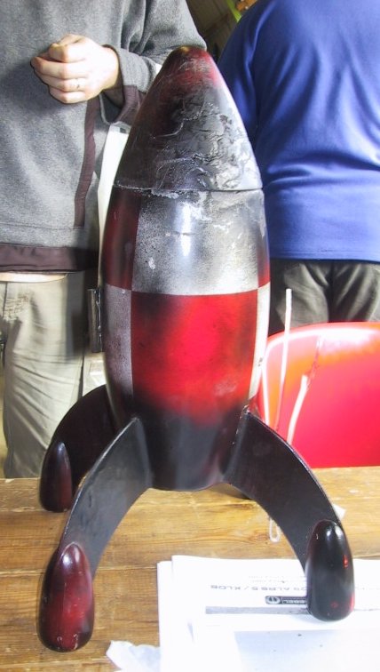
OK, so it's not exactly the right proportions for Tin Tin's rocket, far too squat and stubby, but that's why it's called Tintinique. Just As diamonique isn't diamond, Tintinique isn't Tin Tin. ( Anyone who doesn't know what I'm talking about here, needs to watch more QVC!)
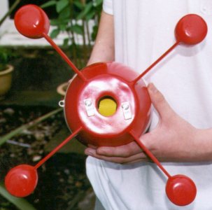
Time Capsules
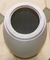
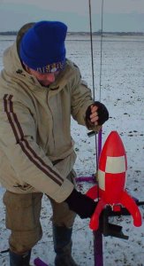
In October 99, I attended K-Lob in Lincolnshire. Amongst the rockets there was something very different. It looked like a 50's retro rocket. It was great. How on earth did they make the body for that? It turns out, that during the run up to the millenium celebrations someone at Nestlé thought it would be a good idea to produce a time capsule in which people could bury stuff, and dig it up in the future. Being Nestlé of course they sold it full of sweets (candy for those of you across the pond). For some bizzarre reason known only to the designer, the capsule itself, was made from a shape resembling the body of a typical sci-fi or cartoon rocket. Better still, the screw-on lid was easily convertible into a removeable nose cone. Whoever it was I'd love to ask them why they did it. I buy two, one for a podded Tin Tin rocket, the other for spare.

Anyway, time passes and every time I go to a launch there's another time capsule. I've got to build this thing. I decide to build it for RMR DesCon6. Time passes. DesCon6 begins. Time passes. DesCon6 finishes. UKRA 2000 approaches, and I realise that the rocket I intended to take, Accusatory Finger of Suspicion, isn't going to be ready. I dig out the time capsule. I dig out cover scans of the books Destination Moon, and Explorers on the Moon. I wonder how on earth I'm going to make the fin pods.
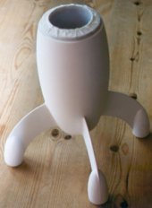
I ignore the question of the fin pods, and start to think about the body instead. Time capsules are cheaply moulded, thick in some places thin in others, and very flexible. I had decided that it was to have a 29mm motor mount to utilise the short 29mm casings I had, and so the body would need to be reinforced. It needs an internal body tube, to give structural strength and provide something to attach other components to, leaving the time capsule to form only an outer shell. I had some 3" plastic tubing that I had got from Ziggy at K-Lob, and this seemed ideal. I could have used standard 3" PML phenolic, or even quantum tubing, but I didn't have any.
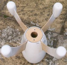
In order to fit the internal body tube into the time capsule I hacked off the screw thread at the open end, and hacked a 3" diameter hole in the base. The opening at the top of the time casule was larger than 3", so I cut a 3mm thick plywood centering ring, and glued it in place, under the shoulder. The plastic tube now fits snugly at both ends.
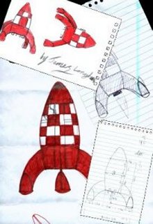
Design
I still don't know what the completed rocket will look like, so I draw some rough sketches, then some rough, dimensioned sketches. My son, James, draws some sketches. I'm not really getting anywhere. It's all free hand and not very satisfactory. Rocksim! The time capsule is suprisingly easy to describe using a parabolic nose cone, and a couple of eliptical transitions. Now, Rocksim isn't really designed for this shape of rocket, and so I'm not going to trust what it says about stability, but at least it helps visualise what the rocket will look like when complete.
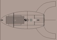
Download the RockSim file
Construction
Motor Mount & Retention
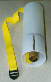
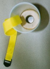
I do have a short piece of PML 29mm motor mount. I had originally intended for the motor mount to run the length of the body, with the space for a parachute between the internal body tube and the motor mount. It doesn't look like enough room for a chute, and anyway I don't have enough motor mount for the full length of the internal body tube. So, I decide to have a short motor mount, giving the full internal diameter of the internal tube for a parachute. I cut two, 3mm thick, plywood centering rings that fit over the motor mount and into the plastic tube. The forward centering ring has a notch to pass a nylon strap. The strap is about25mm wide and 400mm long. The nylon strap will provide an attachment point for the elastic shock cord. The strap is to epoxied to the inside of the internal body tube. Throughout construction I use 5 minute or two ton Devcon epoxy.
The forward centering ring was epoxied to the forward end of the motor mount and allowed to cure. The aft cebtering reing was fitted, with no epoxy, to the rear of the motor mount. The forward centering ring was epoxied into the internal motor mount. Once the forward centering ring was fixed, the aft centering ring was removed. This gives access to the inside of the internal body tube, for filleting.
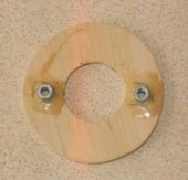
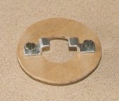
As I'm planning on flying with a 29mm RMS, no thrust ring is required. But I do need a retention system. I decide on a Kaplow Klip style affair. Two M5 nuts are glued to the forward side of the aft centering ring. Then a hole is drilled in the center of the nuts, through the centering ring, taking care to use a small enough drill bit that the threads aren't stripped. Once dry, bolts are screwed into the nuts and through the plywood of the centering ring. The clips are made from aluminium, bent to shape by hammering them over, while held in a vice. The unformed blanks were about 10mm wide and 35mm long.
Fins & Fin Pods
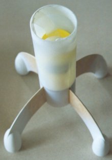
After much sketching, I eventually determine that the most aesthetically pleasing fin pattern (to me anyhow) is such that the fins oposite each other on the body form a semicircle, when viewed side-on. This neccessitated a four fin design, which was fine. I reckoned I needed all the stability I could get. It wasn't consistant with Tin Tin, but what the hey, artistic license! Given the flimsiness of the outer shell, the fins have to be through-the-wall. In the end I descide to make them pass through the wall of the inner body tube too. That way they can be securely mounted to the motor mount. This means that all the major structural elements are glued to each other, giving maximum strength.
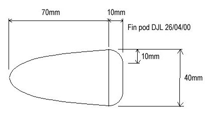
The more I think about the fins pods, the more they seem like a nose cone, but rounded at the base, where the shoulder would normally be. I've had custom nose cones made before. I sketch a plan and get them made by Rockets & Things. I order five, one for emergencies! They arrive within a few days, and I'm well pleased, exactly the right shape, and all identical. But how am I going to attach them?
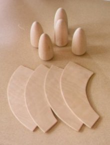
While I ponder this I cut out the fins from 3mm plywood. I leave a large tab for through-the-wall mounting. I'm still wondering how to mount the pods. Shouls I try to slot them and slip them over the fin? Tricky. Cut the fin to the shape of the pod and make a butt-joint? Trickier. Eventually I take the brute force method and saw the pods in half along their vertical axis. The thickness of the saw takes about 1.5mm from the diameter, measure at right angles to the cut. A little sanding, required anyway to level the cut up a bit, removes 3mm in total. When placed on either side of the fin, they are back to the original diameter. The pod halves are simply glued to either side of a fin with carpenters glue, clamped up and left to dry.
Next step is to seal the balsa and plywood. I use several coats of sanding sealer, with a light sanding of 120 grit between coats. Next I fill the joins. I've tried all kinds of filler. P38, specialist modelling filler, Ronseal exterior wood filler all sorts, and they all smell terrible! I found the P38 dries too quickly and sets too hard. The modelling filler is expensive and doesn't stick to phenolic very well. I like the Ronseal best, it was workable longer, and easier to sand, but heavy. I like to fill the spirals in phenolic tubing with this. In the end I use the specialist modelling filler because it's light. I don't need any extra weight at the that end of the rocket! It takes a lot of filler around the join between the fin pod halves and the fin. I apply a few light coats of primer to the pods, sanding between coats.

Fin Assembly
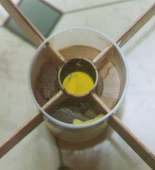
To allow for through-the-wall mounting of the fins, I need to cut fin slots in both the inner body tube and the outer body shell. I use a Dremmel for this with a disc cutter. The slots in the inner body tube are true closed slots for strength. I reason that it will be easier to attach the fins to the inner body tube, before the outer body shell is fitted. If I do that I won't be able to get the outer body shell on, so I make those slots all the way to the bottom. This reduces teh strength, but the body shell isn't really stuctural anyway. The fins are slotted into place in the inner body and epoxied to the motor mount. Epoxy fillets are made where the fins attach to the motor mount, and on both the inside and outside of the inner body. The slots are longe enough to stretch from the forward centering ring to the aft centering ring. This all adds strength, but weight as well. Finally the rear centering ring is epoxied into position.
Nose Cone
I need a coupler tube that will fit into the plastic tubing of the inner body. I don't have any, so make a short tlength from the same tubing. I simply cut out a slot of the correct width to reduce the outer circimference to that of the inner circumference of the opriginal tube. Is epoxy the cut out strip to the back of the join for reinforcement. This tube is first superglued and then epoxied into the nose cone.
Final Assembly
Just in time, I realise that the outer shell isn't going to be strong enough to attach a launch lug to, without some form of reinforcement. I cut a small rectangulat slot in the side of the body shell. I epoxy some plywood to the interior of the shell, behind the slot. The epoxy gunges through the slot, and I use it to fix the launch lug in place.
The body shell slips on easily, and is epoxied initially to just the forward end. Actually the inner tube is glued to the centering ring previously fixed into the outer shell. Because the aft and of the shell is flapping about a bit, I tack it into place with CA. Then I apply a liberal application of epoxy, to the aft end and also to the fin roots. Once it's all set, it gets sanded and filled. The epoxy fillets in the fin roots turn out a bit rough, so I rebuild the fillets with Ronseal. Prime, sand, fill, sand, primne, sand, fill, sand, prime, sand. Or something like that. It's ready. I rub it down lightly with 200 grit wet and dry.
Swing test
Because of the odd shape, I didn't trust the stability factor given by Rocksim. In fact rocksim reckoned it wasn't stable by a mile. But you don't always need more than a calibre of stability on a stubby rocket anyway. I still reckon I need nose weight, but what to use? Lead would be good, but where can I get it and how much is it going to cost, I'll probably have to buy it by the yard! My eldest son, Shaun has the answer, coin of the realm. One pees are quite heavy for their size. I add 200g of weight to the nose. Rocksim says "marginal". I decide that the only way to be certain is a swing test.
Now, this is the biggest rocket I've ever swung test, and it turns out my garden isn't quite big enough, not when the washing is drying anyway. So I comandeer the next door neighbours garden, because they're not in. Needless to say they came home during the swing test, but they're used to it by now. Anyway I start to swing, and it jumps into the right orientation. Great. I do a few more sims, using different motors, and it doesn't go very high. So I reduce the nose weight to about 100g, or to be more exact 31p. Another quick swing test and it's still good. I blue the nose wight into the nose with epoxy. Once the epoxy is dry I realise that I have no where to attach the shock cord to. I drill a hole into the nose weight, fill it with epoxy, and insert an eye hook. Sorted.
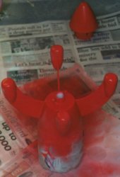
Finish
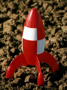
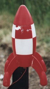
I had been priming as I went along, so as soon as the fin fillets were complete, it only took another couple of coats to get a nice smooth finish. The primer used throughout is Halfords car paint, in the aerosol cans. I also use Halfords for the main colours. Rover Diamond White and Volkswagen Mars Red. Seems appropriate really. First I spray the whole rocket white. I do about 3 coats, lightly sanding between each. I had decided much earlier on that a full Tin Tin chequerboard was far too much work, so I had scaled the pattern down to two bands, of four quadrants. First I masked off every thing above the fins, and painted everything below red. I also painted the nose cone. The red covered really well in only two light coats. Next I painted the two red quadrants of the lower band. So far so good. The red quadrants of the upper band were hardest, bacause it was hard to get a the masking tape into exactly the right position to make the square corners of red meet exactly. The masking was the hardest part of the entire project. The red paint crept underneath the tape in certain areas, and in other areas the tape lifted off some small areas of white when removed. But I managed to touch those defects up, and I'm pretty pleased with the final outcome. It's the best finish of all the rockets I've made so far. It needs going over with 400 grit wet and dry and a coat of lacquer applying, but there's no time. UKRA 2000 starts tomorrow!

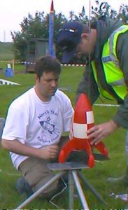
Flight Test - UKRA 2000
I use about 150mm of nomex sheath over the nylon strap, and a nomex sheet above that to protect the chute. About 70mm of 20mm elastic attach the nose cone to the nylon strap. A 34" PML chute is atached to the elastic too. I decide upon a G104 blue thunder reload. It's only just a G, but it gets the rocket moving quick. I reckon the sooner I can get it up to stable speed the better.
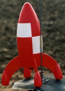
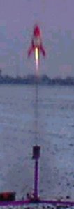
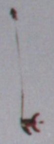
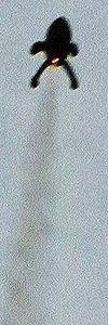
It rains on Friday and Saturday, and I'm hesitant to fly. Sunday is better, and I decide to fly before I take up spotting duty. On the Staryrday I'd had it on a rod, and found it was a little tight, but I had found a slightly smaller diametr rod, which was perfect. I was pretty nervous during the countdown, and we had a hold for a low flying aircraft, but finally, the moment comes. 5, 4, 3, 2, 1 ignition. It's away! Great flight! It arced a bit after it left the rod, but very smooth, no sign of a wobble or instability of any kind. The ejection fired right at apogee, and Tintinique drifted slowly down, landing approximately 40" from the pad. There is a little damage to the nose cone,I can't figure out if it happened in flight or on impact with the ground, but I couldn't find the piece chipped out so it probably happened in the air. Easy to fix, next flight coming soon...


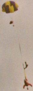
IRW 2000, Largs, Scotland
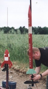
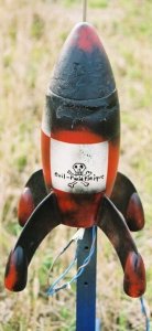
Tintinique is now an established flier. The small amount of damage from the first flight was restricted to the nose cone and was repaired with a little fibreflass and finishing epoxy. It has since been flown at the IRW (International Rocket Week) in Scotland, here are the pics. The last flight resulted in the launch lug being ripped open. This was after an attempt to fly on a G80. I don't know if it just bound on the rod, or was a bit underpowered.


K-Lob 2000, Lincolnshire
The damaged launch lug has since been replaced with a more solid brass one, and the rocket flown again at K-Lob 2000.
Copper Knobs 2000, Lincolnshire
The NSRG's annual HPR event. A few of us go down to Pete's and, weather permitting, fly some stuff. This year's event was very cold. Brrrrr.
Brass Balls 2001, Lincolnshire
MARS's annual bash. Unfortunately no pictures of this event. Also very cold, and very foggy too. Some might say too foggy! Footage of this event, including the launch of Tintinique was imortalized forever by the producers of the "detonators" TV program, subsequently shown on the Discovery Channel. Unfortunately I don't have a copy.
UKRA 2001, Lincolnshire
No pictures of Tintinique from this event!
BigEARS 2001, Cambridgeshire
Time for something bigger! A temporary shortage of G104s led to an experiment with an H238. The resulting flight was so cool, I just had to do it again. And again! Picked up a bit of damage, mainly due to a partially deployed chute - cosmetic and nothing structural. Still, the ploughed fields were fairly forgiving.
IRW 2001, Largs, Scotland
No flight pictures from this event either, but Tintinique did manage to get into the article written about the event that later appeared in the Scotsman. The flight itself was textbook, half way up the mountain that was the temporary home of IRW HPR, but it managed to find the only rock in the valley below to land on, cracking a fin. The crack was easily repaired with a wrap of fibregless.

K-Lob 2001, Lincolnshire
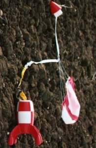
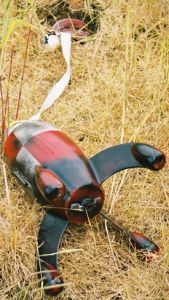
It had to happen sooner or later, Tintinique is badly broken. A very late deployment led to the shock cord snapping. The body plummeted to the ground, which the chute and nosecone drifted off towards Sleaford. A fruitless[1] search for the nosecone and chute ensued. The fin snapped off at the root of the body shell. It's not a clean break, and it's not going to be an easy repair.

[1] Later however, a fellow rocketeer, on his way home, spotted the parachute billowing in a farmer's field. He stopped, collected it, and brought it back to the event for me. Thanks Steve!
Goodbye Tintinique, hello Evil-Twintinique
Well, it appeared to be all over, and, truth be known, I was a bit upset about it. Some very good friends of mine even organised a wake, which was very nice of them. You can see it here.
Well, the wake turned out to be a bit premature. After much agonising and a brief burial beneath hallowed turf, something came back. Tintinique, or at least a close relative, a sort of Evil-Twintinique.
UKRA 2002, Lincolnshire
Flying on a jinxed [2] motor, this was never going have a happy ending. I had intended flying on a my last H238 later, but, as it turned out, that was going to have to wait for over two long years...


[2]Yeah, jinxed! If you don't believe me, take a look at the complete flight stats below. Does it look like this rocket has had a good record with the G80?
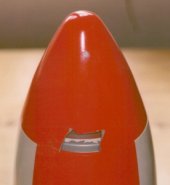
K-Lob 2004, Lincolnshire
The muse had lain idle for too long. The rec.models.rockets descon 14 1/2 was just the impetus I needed to put the wheels back on the bus, or at least to CA together the pieces of the nose cone and fill the gaps with fibreglass, epoxy and filler. After all, why had I been hinding the last H238 in the UK in the bottom of my ammo box, resisting all would-be purchasers, if not for this very moment?
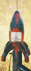
It turned out to be a very quick rebuild. Other than the nosecone, the damage was entirely cosmetic. The body shell was a bit wrinkled and more paint had come off. The nose cone was fairly painless too. I used CA to put the pieces I had back together. The nose cone shoulder/coupler was reattached with west systems epoxy bulked up with a little filler. The remaining holes in the nose were filled with a mush of the same epoxy and scrap fibreglass. In the morning, I gave it a rough going over with the dremmel, and a quick spray of black paint. The effect is quite good. It looks as though it's been on fire! I reckon it would make an effective finishing technique for a very evil-looking rocket!
It felt very odd assembling the 29mm Aerotech reload. It's been a long time what with 9/11, the fire, the inablity to come to terms with CE marking - these motors are scarce! I took the nostalgia too far though, by attempting to use the copperhead to light what was after all quite old AP. Needless to say it didn't work. Neither did the home made igniterman. In the end I dipped an e-match, attached some pic slow, and redipped the whole thing. What a flight! I had forgotten the speed something that fat could get off the pad! Still, managed to get what is probably the best in-flight pic to date. Recover was text book. If Aerotech can get their stuff back into the UK, then I'll be queueing up to buy more - the redline would be awsome!


Complete flight log
| Date | Location | Motor | Comments |
|---|---|---|---|
| 04/06/00 | UKRA 2000, Garlands | G104T | First flight, damage to rim of nosecone |
| 24/08/00 | IRW 2000, Largs, Scotland | G104T | With the nosecone repaired another great flight, and this time no damage |
| 26/08/00 | IRW 2000, Largs, Scotland | G104T | Third time, still lucky, this flight it landed upright on it's legs |
| 27/08/00 | IRW 2000, Largs, Scotland | G80 | CATO! The motor casing popped and the nose cone raised slightly, but no damage |
| 28/08/00 | IRW 2000, Largs, Scotland | G80 | Bound a bit on the rod, ripped the lug off and shot horizontally across the field. Amazingly only the lug was damaged |
| 01/10/00 | K-Lob 2000, Lincolnshire | G104T | Back on the motor of choice |
| 29/12/00 | Copper Knobs 2000, Lincolnshire | G104T | A very long delay almost meant disaster. Deployment was approx 20', but only minor scratches resulted |
| 20/01/01 | Brass Balls 2001 | G104T | Pretty foggy, didn't lose sight on the way up, but on the way down! |
| 16/06/01 | UKRA 2001, Lincolnshire | G104T | That's it for the G104, now for something bigger! |
| 01/07/01 | Big EARS, Cambridge | H238T | What a blast! |
| 01/07/01 | Big EARS, Cambridge | H238T | Chute didn't deploy, more chipped paint and a crack at teh base of the body |
| 01/07/01 | Big EARS, Cambridge | H238T | Another excellent flight |
| 23/08/01 | IRW 2001, Largs, Scotland | H238T | landed on rock and cracked a fin - repairable |
| 30/09/01 | K-Lob 2001, Lincolnshire | H238T | Bonus delay - shock cord broke - plummeted from sky and broke a fin clean off |
| 08/06/02 | UKRA 2002, Lincolnshire | G80 | No ejection charge on this flight meant a ballistic landing. The G80 does not like this rocket! |
| 25/09/04 | K-Lob 2004, Lincolnshire | H238T | Very old motor took some lighting, but it went in the end. Great flight, no damage - if only I had more 29mm AP! |
Darren J Longhorn is a member of the North Star Rocketry Group and the United Kingdom Rocketry Association