 |
 |
 |
 |
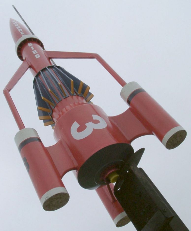 |
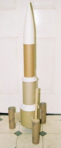
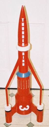
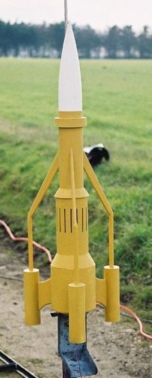
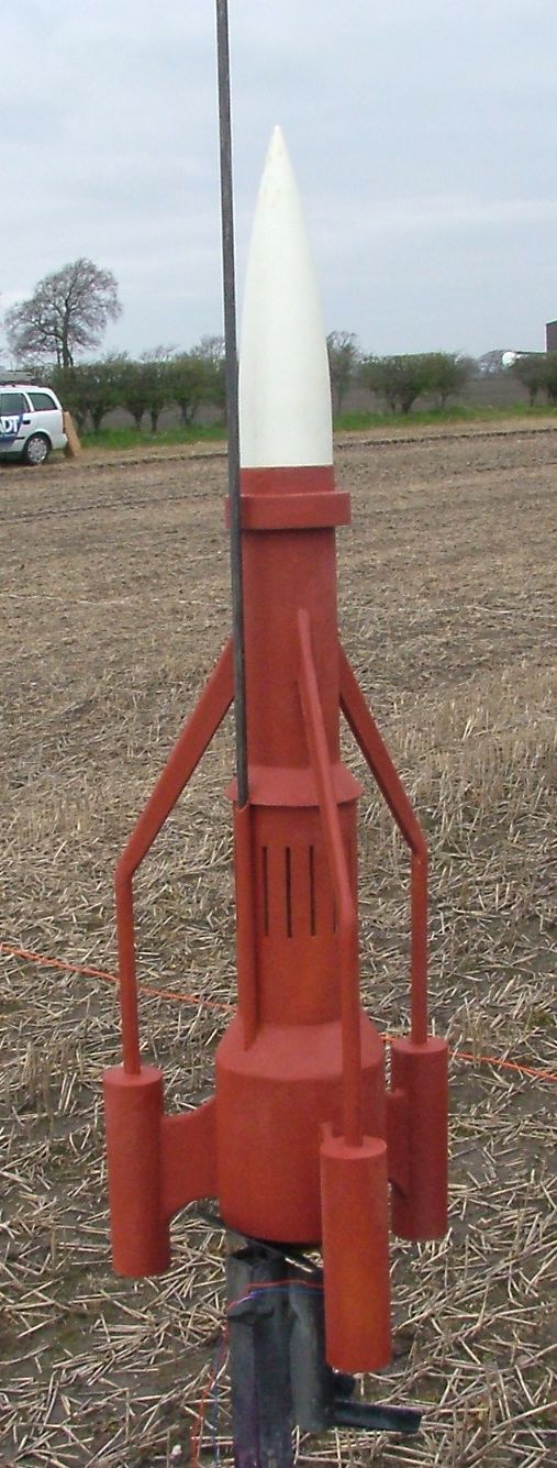
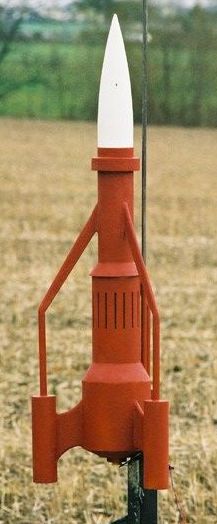
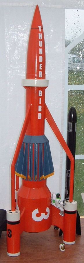
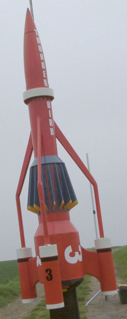
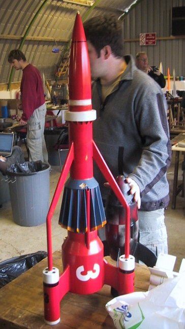
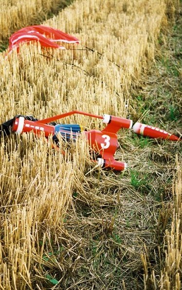
Thunderbird 3
by Darren J Longhorn
I'd been looking to build a general purpose G/H/I powered rocket for general flying for some time. After a long building hiatus, my HPR fleet had decayed until I had nothing in a flyable state! I wanted something that would be suitable for general sport flying. I didn't want a rocket that would be going very high, or require extensive prepping. So anything requiring CPR or electronics was out. It had to be something interesting, not just 3FNC, and it had to make a dent in the tube pile in the corner of the room. So, the requirements were:
- Mid to HPR
- Interesting to build
- Easy to prep & recover
- Eye catching
At the beginning of December 2003, the trailers for the forthcoming Thunderbirds film began to appear. There was lots of debate about how good it was going to be on some of the news groups and mailing lists to which I subscribe. The new design Thunderbird 3 was appealing, but I would have a hard time producing a working drawing from the short trailers. It did, however, prompt me to reread the Thunderbirds section in my copy of "Spaceship Handbook" by Jack Hagerty & Jon C. Rogers (if you're not familiar with this book it's basically a "Rockets of the Fictional World"). This excellent publication features scale drawings of Thunderbirds 1, 3 & 5. Again, it was Thunderbird 3 which caught my eye, which was always my favourite Thunderbird when I watched the Gerry Anderson series as a kid. I've also admired the Thunderbird 3 models flown by Adrian Hurt and Mike Crewe.
Design
Sources
As mentioned in the intro, my primary source for this project was the scale drawing of TB3, by Jon C. Rogers. I also used the model rocket plans by Tom Beach for inspiration. There are also many, many images of TB3 available on the web. Some of these are listed in the links at the end of this article.
Scale
The model makers working on Thunderbirds built several models, of varying size, of each vehicle, which were used for the various scenes in which each vehicle appeared. So one size for the launch scenes, another in flight, landing or docking and so on. That's fine, but unfortunately, these models were often used inconsistently, with the regard to the relative scale of their surroundings. This gives the vehicle depicted the appearance of being larger, or smaller, depending upon the scene. Working out the "actual" size of the vehicle is therefore technically impossible. Jon admits this in the Thunderbird 3 drawing notes, which state: "This drawing is a composite of several scenes and represents the best data available". This composite drawing then, which is as good as it gets, gives an overall length of 4108 inches.
Incidentally, if you think this problem with scale from scene to scene was a bit amateurish of Gerry Anderson's model makers, then look carefully at the docking scene the next time you are watching 2001. The Orion is much smaller, relative to the station, than it has any right to be!
So that's the length of the prototype sorted. How did I decide what scale to build at? Well of course I didn't. When scratch building, you might expect to be able to choose the scale you build at. But, unless you are prepared to roll your own body tubes, the scale is usually determined by the diameter of the available body tubes, and this project was no exception. So what scale is it? As I'll explain later, various compromises were made along the way and some dimensions are either slightly over or under scale, but, everything is built around that main body tube, which is 80mm in diameter. The drawing gives this diameter as 345 inches, which gives us a scale of:
      scale = model diameter / prototype diameter
            =          3.15" / 245"
            =              1 / 109.54
Let's call that 1:110 scale. It was at this point that I realised just how big the "real" Thunderbird 3 is meant to be! Much bigger, I think, than is suggested by the scene in which it flies through the roundhouse on Tracy Island!
An aside:
|
Selecting Tubes
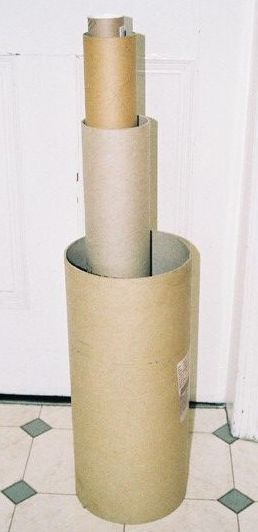
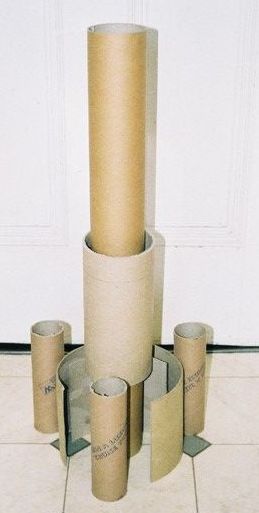
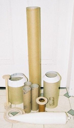
In the corner of my "office", at home. I have a huge stash of cardboard tubes, and so I had plenty of tubes to choose from. A quick look at the drawings shows that Thunderbird 3 has three main body diameters: the forward section, the aft section, and the central "radiator" section.
When choosing body tubes for any scratch building project, one of the most important selections is the diameter of the tube that will mate to the nose cone. Without the right equipment, scratch building nose cones is either time consuming, or expensive. So I wanted to pick a diameter for which a nose cone would be readily obtainable. I initially considered a forward body diameter of about 2.6 inches. I had a tube for that, but when I worked out what that would require for the aft and centre sections, I was out of luck. So I went up a size to approximately 3", or 80mm. This worked out quite well. I had a suitable tube, and the required diameter of the centre section worked out to be 107mm, with the aft section 151mm. 107mm is approximately 4" and I had a selection of tubes near that size. The aft section was more problematic, and I didn't have a near match. I did have a larger diameter, approximately 210mm in diameter, which, I thought, could be cut down to the right size. I've attempted this technique before, with various degrees of success. But, the larger the diameter, the better the results, and I decided it was worth a gamble.
I decided that I would make the docking collar from the same diameter tube as the centre section, to avoid having to make a custom size. It's actually meant to be a bit bigger diameter, but I don't think it's noticeable enough to worry about.
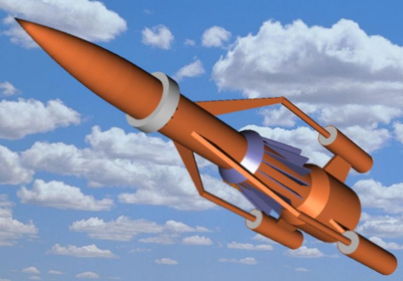
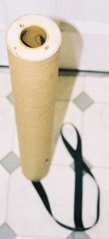
Pods
The rocket pods on Thunderbird 3 have a curved profile. I considered modeling this, but realised it would be difficult. I could think of two main ways to construct them, either turned from balsa, or hot-wired from expanded polystyrene. Since I don't have a lathe, I would have to buy turned balsa, which I knew from experience can be quite costly. I do have every intention of building a hot-wire "lathe", but it's one of those jobs that I never quite get around to completing. So, I decided that it wouldn't be too much of a compromise to use straight tubes.
The pod diameter should vary from 37mm at the ends to almost 67mm at the widest point, but I figured that as long as I used a tube diameter between those two figures that it would be close enough.
Nose Cone
I figured the required nose cone was a 3:1 ogive. These aren't as common as you might think. PML and LOC plastic cones are both longer than 3:1. In the end I found 3:1 ratio balsa cones from US Rockets. Despite what reading r.m.r might lead you to believe, I found Jerry Irvine to be very easy to deal with, and the quality of the cones is very good. We did have a few problems with international money transfer, but nothing that we couldn't sort out. But, in the interim, I got a LOC cone from NSRG colleague Brian Best, which is what I used. This means my Thunderbird 3 is longer than it should be, but when I get the chance I'll replace it with the USR cone.
Transitions
The biggest worry I had were the transitions. They transitions between the aft and centre sections and the centre and forward sections looked easy enough, but I immediately decided that the curved profile of the aft end of the rocket wasn't going to possible. That being the case, I decided to make that as a simple truncated cone too. The easiest way I could think to make them was from cardboard, strengthened with fibreglass. That was what worried me! My fibre glassing experience is very black and white. It either goes very well, or ends in disaster. In this case I was to be pleasantly surprised.
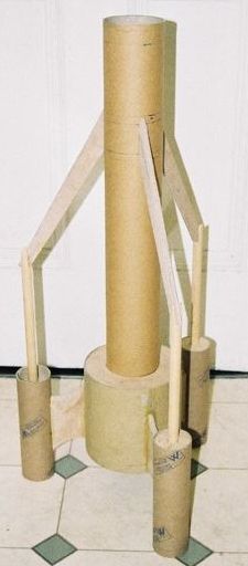
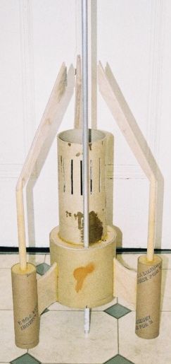
Structure
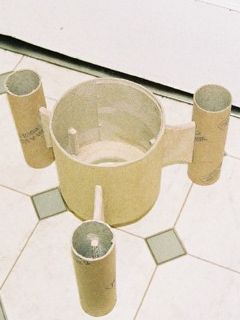
Once I had the size figured out, I had to decide how it was all going to go together. For simplicity, I decided that the forward body section would be extended to run the full length of the rocket, becoming the "main" body tube. This meant that everything else could hang off this, via centring rings.
Two large centring rings are used to attach the aft body tube. The centre section sits directly on top of the aft section's forward centring ring. As the centre section's forward centring ring is of larger diameter than the centre section itself, this means the centre section isn't really centred by the rings, and had to be manually located. The centre section's forward centring ring was also bevelled to allow for easy positioning of the forward/centre transition. Centring rings internal to the main tube are used to centre the motor mount. A small centring ring forms the forward end of the docking collar.
I decided that I would use wooden dowels for the pillars, centred in the pods with more centring rings. The buttresses would be cut from the same plywood as the centring rings
Stability
RockSim is a great program, but you have to wonder how accurately it can predict CP for a shape as complex as this. I did have a sanity check available to me though. Spaceship Handbook has a set of plans for a smaller version of Thunderbird 3, designed by Tom Beach. These plans clearly show the desired location of the CG. Now, as any rocketeer worth his salt will undoubtedly know, CP does not change with scale, only with outline. so if I placed my CG in the same scale position as shown in Tom's plans, my CG would be in the same position relative to CP as Tom's. The plans show the CG to be approximately 55% of the overall length from the tip of the nosecone. This puts the CG at the top of the centre section "radiator" fins.
As it turned out, it was good to have this calibration check, because RockSim put the CP in roughly the same location as Tom located the CG! I don't know how Tom worked out where to put it. Probably by 'eye' or trial and error. Anyway, regardless of what RockSim was telling me, it seemed that the real CP out to be further back than that, it's a pretty draggy shape, after all. What had become overwhelmingly obvious was that I was going to have to add quite a lot of nose weight! For the included Rocksim file (see link below) I had to override the weight and CG location to get it to "fly right". So if you take a look at the file, ignore the location of the CG & CP!
Motor Mount
At the design stage, I wasn't sure of what the impulse requirement might be, but I was hoping to be able to fly on G, H & I engines. Given the current motor availability situation in the UK, which is pretty much limited to Cesaroni, meant that Pro38 would be the most likely motor type, and so I chose a 38mm motor mount. The way things worked out weight-wise, a G impulse motor isn't really powerful enough, leaving H & I engines as the most likely choice, though low J is a possibility.
In the "real" TB3 the engines are in the pods. The vast majority of people who have seen this model have suggested that I "should have put the motors in the pods". Replicating this feature of the prototype would obviously have been very cool, but I don't have much experience of clustering AP, and I wanted something simple. Also, the wide separation of the three motors would mean that failure of any motor to ignite would lead to an unsafe flight. I just didn't want to risk it and went instead, for a single motor positioned, unprototypically, in the centre.
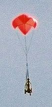
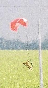
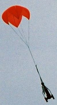
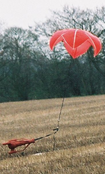
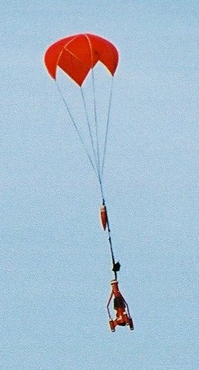
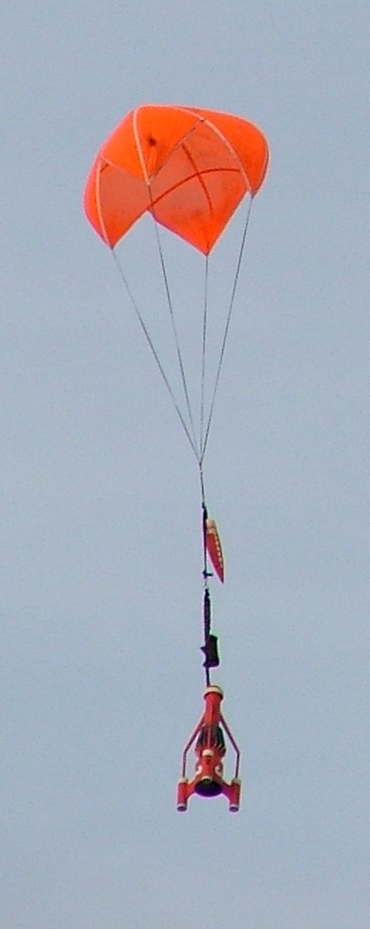
Recovery
Again, because I wanted something that was easy to prep and fly, I didn't really want to be bothered with any kind of electronics. So that ruled out CPR and meant that the recovery would be of the "all out at apogee" type, using a motor ejection charge. I had hoped that I would be able to use a 34" PML chute, of which I have several. I did use one of these on the first flight, but the descent rate was just too great. For the subsequent flights, I borrowed a large RocketMan chute from Brian Best, which worked very well.
Fabrication
Body Tubes
Once the tunes had been selected and the design finalised, the first job was to cut the tubes to length. This list of tubes to cut was main body, centre section, aft section, docking collar, and the three pods. To mark the cut, I wrapped paper around the tube, then used the edge as a guide for the pencil line. For body tubes of this size, I use a junior hacksaw to make the cut, and this was no exception. I went around the whole diameter first, making a shallow cut. I find this helps guide the blade when making the final cut.
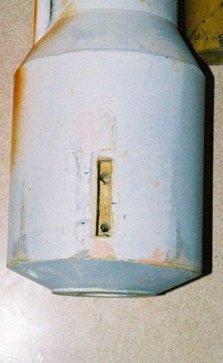
To create the aft body section I cut out a section of a larger diameter tube. This is quite easy to do, mainly due to the large diameter. Smaller diameter tunes are much trickier and tend not to be circular. First I drew a vertical line along the length of the large tube. Then I calculated the desired circumference and marked this on a piece of paper. The paper was wrapped around the tube and this allowed the marking of a second vertical line. The are contained within these two lines was then removed.
The next stage is the trickiest. The curvature must be increased until the ends butt together. To induce this curvature, the cut tube was rolled progressively tighter and held in position. By rolling the tube tighter than is required, the tube was "trained" into the new curvature helping to hold the desired diameter when released. This had to be done gradually, or a kink would have developed resulting in a decidedly non-circular tube! Once the increased curvature began to hold, the removed section was glued onto the inside of the new tube, and clamped in place. This acts as a strengthener.
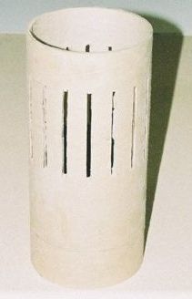
Many people see tube slotting as a chore, and even though I quite enjoy it, it was a bit labourious here! There are three slots where the fins join the aft section, one on each of the pods, three on the forward section, and no less than 16 on the centre section. It was this centre section which was by far the most labourious. All the slots were cut using a cut-off disc in my Dremel. This is reasonably easy to accomplish, if you have a steady hand. You need to keep the disc parallel and a moderate feed rate, otherwise the disk will shatter. I got through quite a lot of disks!
Muzak to build by [~3Mb mp3 format]
Centring Rings
I have a bit of a bee in my bonnet about centring rings. Many people seem to get hung up on the best way to machine cut them, designing elaborate jogs. It just seems too complicated to me. I use a pair of compasses to draw the circle, and then cut them out free hand using a coping saw. It gives me a feeling of great satisfaction.
Using the above "technique", I cut out two rings for the aft section, the mid-section ring, the docking collar, two for the motor mount and six for the pods. All of the centring rings were cut from 9mm plywood, which was perhaps a little on the thick side, but it was what I had.
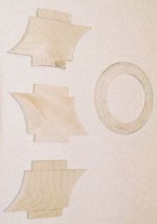
Transitions
I used VCP to print out templates for the transitions. VCP is a great program that has been overshadowed by RockSim in recent years, and I find that many newcomers to the hobby have never heard of it. Whilst it is nowhere near as sophisticated as RockSim, it's a cheap (The price is certainly right - free!) tool for predicting CP, and it produces really great transition templates, something that RockSim has only been able to do since the release for version 7.04. Even then, VCP's templates are nicer, as they have tabs and slots to help alignment of the ends. The beginner can get a long way using just VCP for stability prediction, and wRasp, for altitude prediction, before lying down the cash for RockSim.
I printed the templates out on paper, cut them out and then transferred them onto card. The card was cut out and used as a template to mark the fibreglass, cutting an extra bit at the tab end to ensure a small amount of overlap. Next, with the template layed flat, I painted on the epoxy resin, and laid the fibreglass on top, working the epoxy into the weave with a brush. Before the layup cures, the transition was formed, the cardboard tab being glued with CA to help hold the shape. Then a little more epoxy is brushed onto the fibreglass overlap. This overlap helps strengthen the transition at the joint. Once dry the ridge created by the overlap was sanded out.
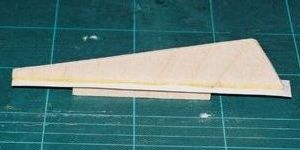
Fins & Things
The main fins were cut from the same 9mm plywood as the centring rings. I roughly rounded the edges with the Dremel's sanding drum attachment, and then smoothed them off by hand. I had initially meant for the fins to have full length tabs, but I inexplicably cut them short, which led to problems later.
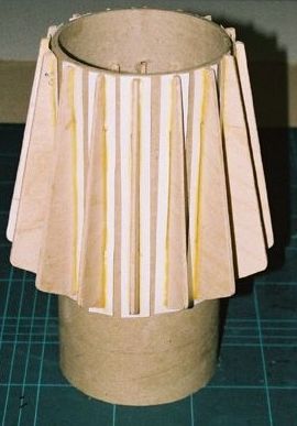
The "buttresses" that attach the forward body tube to the pods were made form two parts. The forward parts were cut from the same 9mm plywood. The rods that attach the pods to the buttresses were cut from 15mm diameter pine dowel. I deliberately cut them over length at this stage, to allow for adjustment to compensate for any cumulative inaccuracies in measurement.
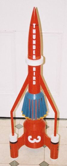
The fins on the centre section were cut from much thinner 3mm plywood. I usually don't mind cutting things out by hand, but sixteen of anything is a real chore - it felt like my arm was made of lead when I'd done. These fins sit on a backing rectangle that is the same colour as the fins, rather than the rest of the body. I realised that this would be almost impossible to mask, so decided to add a physical backing to each fin. This assembly could then be prepainted. These backing rectangles were cut from card and then stiffened with CA. This worked reasonably well, but if I were doing it again I would cut them from styrene sheet. Once assembled, they were given a liberal coating in finishing epoxy in an attempt to cover up any blemishes.
The tiny braces that sit under the docking collar were cut from 2mm thick plywood, and again were prepainted, to avoid a tricky masking problem later.
Assembly
Main Assembly
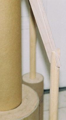
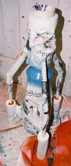
Once all the parts were complete, I did several dry fits, to work out the assembly order. First I attached the fins to the aft body section, then attached the pods. I used wood glue throughout. More dry fitting was done at this point and I realised that there had been a measuring mistake, somewhere along the line. The pine dowels were dry fitted into the centring rings of the attached pods, as was the main body tube into the aft section centring rings. It became obvious that the 'flying buttresses' that run from the forward section to the pod dowels didn't fit properly. The dowels were too long and the span of the buttresses too wide. It was easy enough to modify the existing parts, rather than having to make new though. At this point I sorted out the joint between the dowels and buttresses. I did this by putting notches in the top of the dowels, the width of the buttresses. Once glued together, they were roughed into shape with the Dremel before being finished by hand with sandpaper.
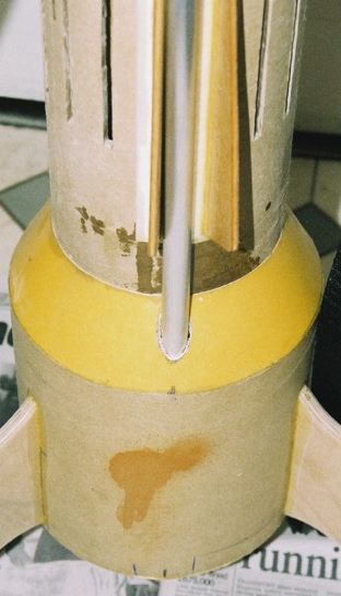
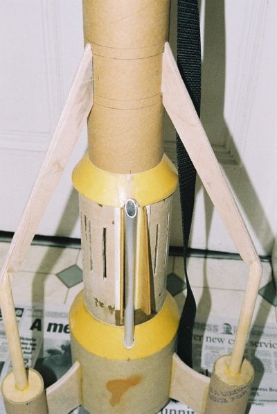
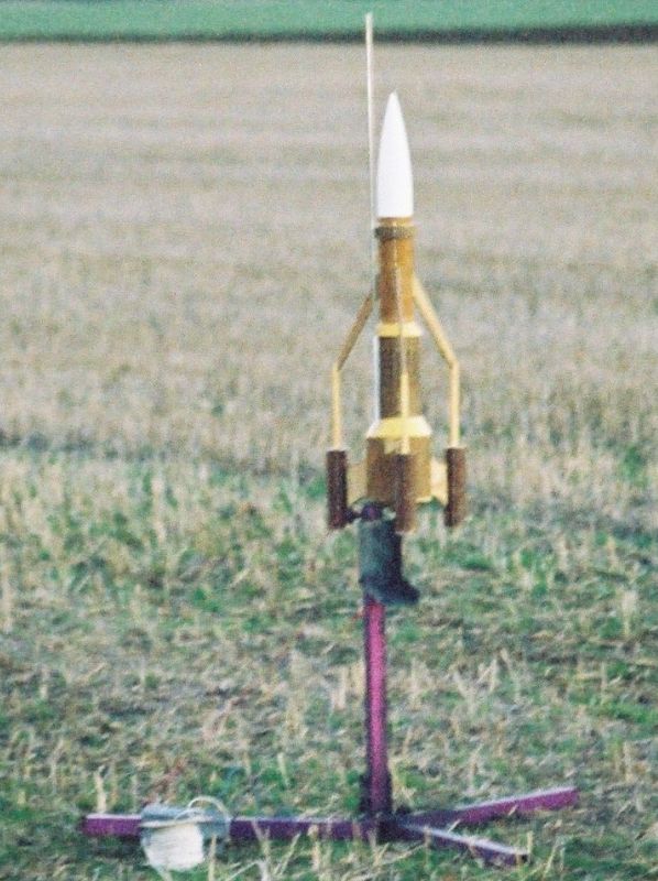
It was at about this stage that I wondered about a launch lug or rail buttons. For me that's not bad. I've been known to take rockets to the launch pad with no means of guiding that first crucial section of the flight. Despite being recently attracted to rail buttons, I decided that they weren't really practical for this rocket. They would have to be on The aft body section, which isn't very long relative to the overall length. For the same reason, it wasn't an ideal location for a launch lug, either. I decided that the only real option was a semi internal lug that would run from the base of the aft section, out the top, between two centre section fins, finishing at the centre section forward transition. I used some nice aluminium tube that is just over 3/8" internal diameter. The hardest part was cutting the hole in the transition between the aft and mid sections.
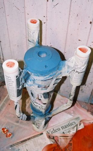
Next, the aft section forward centring ring, with freshly drilled holes for the launch lug, was installed, as were the forward centring rings in the pods. The dowel/buttress combinations were now glued into the pods, using dry fitted aft pod centring rings and main body tube to get the angular positioning correct. The centre body section was glued into position on the aft section centring ring. The nylon shock cord was now glued to the motor mount, and then the centring rings were added. The forward centring ring being notched to fit over the shock cord. The motor mount assemble was then glued into the main body tube.
The internal voids of the pods and aft body tube were filled with expanding two part foam. Once this had dried, any surplus was removed and the rear centring rings fitted. This helped secure the short fin tabs and the launch lug. The void under the rear transition was also filled with foam to add strength, as the fibreglass was still fairly flexible..
Next it was time to fit the transitions. The main body tube was removed, and the two card/fibreglass transitions, plus the forward transition were threaded on before the main body tube was returned to it's final position, using The launch lug to get everything in The correct alignment. I realise that I had nearly made a huge mistake at this point, as I had paid no attention to alignment when locating the centre section. I almost had the launch lug running through a fin! Glue was now applied to all of the parts and allowed to dry.
Final Assembly
Once the final layer of paint was on, the centre section fin assemblies and the docking ring support brackets were glued into position. I used CA for the supports and Elmers PVA for the fins. I also tackled the black discs on the front of the pods. These were made from drawing pins, painted black, inserted into pilot holes and secured with CA.
Adding Strength
After the flights at EARS (see flight log below), I realised that my design & construction just wasn't strong enough to survive the landings. So I removed the fins, pods and buttresses and thought about how I could add reinforcement. It was crazy not to have done full through the wall to the motor mount fins in the first place, but I hadn't, and needed a substitute. The technique I settled upon was to "extend" the fin tabs using carbon fibre rod. I drilled holes into the ends of the tabs on the fins, and into both the aft body and the pods. The holes drilled into the pods penetrated both the expanded foam and the central dowels, while those in the aft body went as far as the inner (main) body tube. I used west systems fibre glassing epoxy to attach the carbon fibre rods, mainly because the thin consistency meant it was easy to get into the drilled holes. As an additional strengthening measure I added fibreglass "fillets" to all the fin roots, followed by traditional epoxy fillets.
Finishing
One of the drawbacks of scratch building with cheap tubes, saved from the dustbin, is that finishing requires more work for the same result. The surface of these tubes tends to be very unstable, with a very prominent spiral. The first thing I did was to paint all of the tubes with finishing epoxy. I've had good result using this method in the past, but not this time. I think the epoxy may have been a bit old, as it went on very lumpily. The layer of finishing epoxy was an attempt to seal the cardboard tubes and level the surface a bit. It was only a partial success. It was nice and sandable, but didn't really smooth out the surface much, even when I had removed The lumpy bits! Any attempt at serious sanding soon went through to the cardboard. However, with a couple of coats of high-build primer, the odd spot of filler, and the attentions of an orbital sander, it looked reasonable presentable.
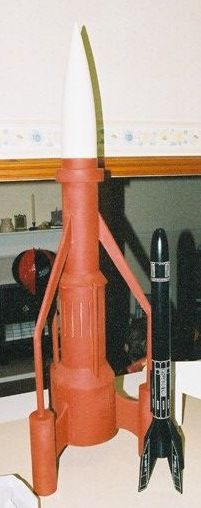
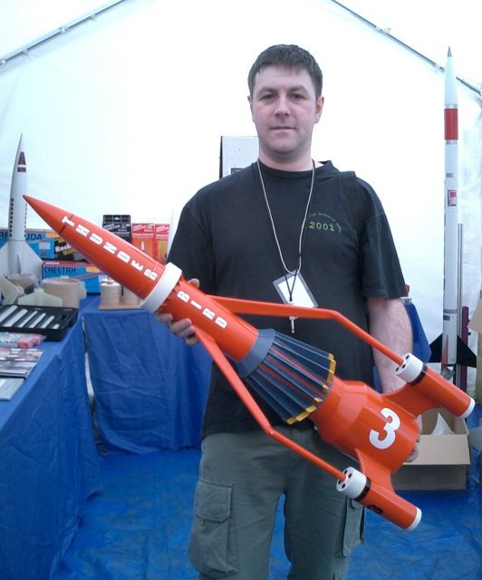
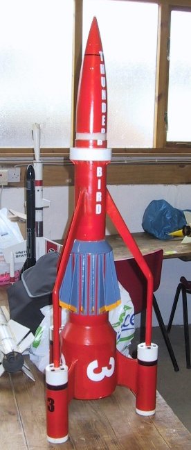
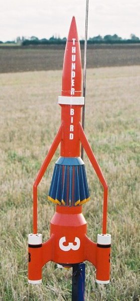
I actually "finished" the rocket four times. The first flight had the rocket in naked finishing epoxy, the second and third flights were in high build primer, and the fourth flight in red oxide primer. There's a lot of primer in there! I tend to use Halfords rattle cans. They're not the cheapest, nor the best, but it is convenient, and their high build primer hides a multitude of sins! One problem was determining the colour. In my memory it's most definitely orange, but Spaceship Handbook says red. A search of the internet revealed a myriad of pictures in all shades from orange to red. I could see that whatever colour I painted it, there would be people that say it's wrong, so I went with what I preferred, orange. The actual colour is Rover Blaze. I think that this is the colour British Leyland used on Minis around the mid to late 70s. It's a bit redder than the Volkswagen Brilliant Orange that I normally use. The other colours are Vauxhall China Blue for the centre section fins and forward and aft transitions, and Rover White Diamond for the docking ring and pod trim ,all Halfords rattle cans.
The decals are vinyl. I drew them using PaintShop Pro and had them cut out by a friend of the Waddingtons. Not bad for the cost of a Marks & Spencer gift voucher. I got enough of the markings for the nose, so that I can do two nose cones, the plastic LOC one and the balsa USR one, if I ever get around to using that. For the black strips, rather than another mammoth masking session I turned to Halfords self-adhesive automotive "go faster stripes". The stripes on the pods are 12mm and the stripe on the nose 3mm.
For the final finish I sprayed on a coat of Halfords general purpose lacquer. Once that was dry a coat of polish was added. I used Johnson Klear for this, which, for those of you across the pond is the same as Future. I sponged this on, taking care to remove any bubbles before it dried. This added a really nice shine that can be seen in some of the photos. I was also going to use the 12mm stripling to do the black "strakes" on the buttresses. I tested this out, and it looked ok from the front, but somehow unconvincing edge-on, so I omitted them. However, as I wrote this article, a kind poster from the starship modeler web forum pointed me to some excellent pictures of one of the original models, which appears to use a very similar technique.


Conclusions
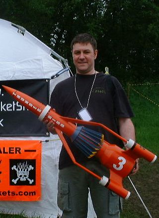
This was an interesting project to both design and build. I met all of my initial criteria, apart from the ability to be flown on a G class motor. It has been a real head turner at launches, and flies great on Pro38 H and I class motors. Anyone fancy building a Thunderbird 1 to drag race against?
I've enjoyed putting this together, that I'm, almost tempted to build another, including the details I omitted from this one, such as curved pods, thrusters on the forward transition, ribs on the docking ring. If I were to have another attempt, I would certainly make provision for some sort of effects devices in the pods. I envisage that good results would be achieved using a short duration, high thrust motor located in the main body for lift off, together with long duration, smoky motors in the pods.
Another interesting point to note is the similarity in size of the main tube diameters, to readily available commercial tube sizes. Using 3" for the main body, 4" for the centre section, 6" for the aft section and 2.1" for the pods, plus associated centring rings, a very good facsimile could be built from PML parts. The transitions, however, would still have to be custom made.
Links
- Thunderbird 3 RockSim file
- One of the original models
- Official Thunderbirds site
- TV Century 21
- Spaceship Handbook
- Resin Thunderbird 3 model kit
- Scratch built Thunderbird 3 model
- "The way of the tube"
- "The tube is civilization"
- RockSim
- VCP
Flight Log
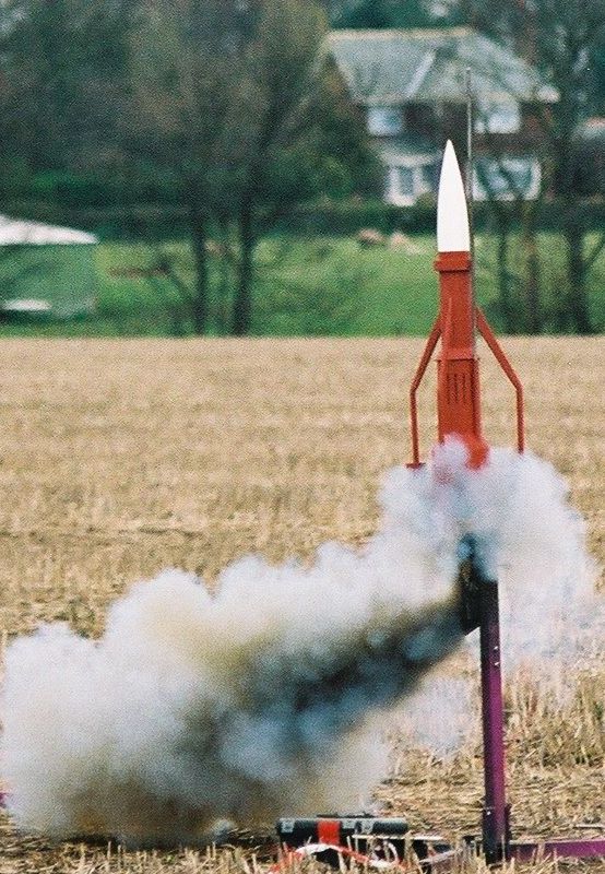
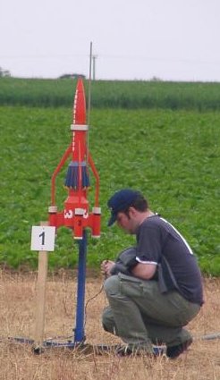
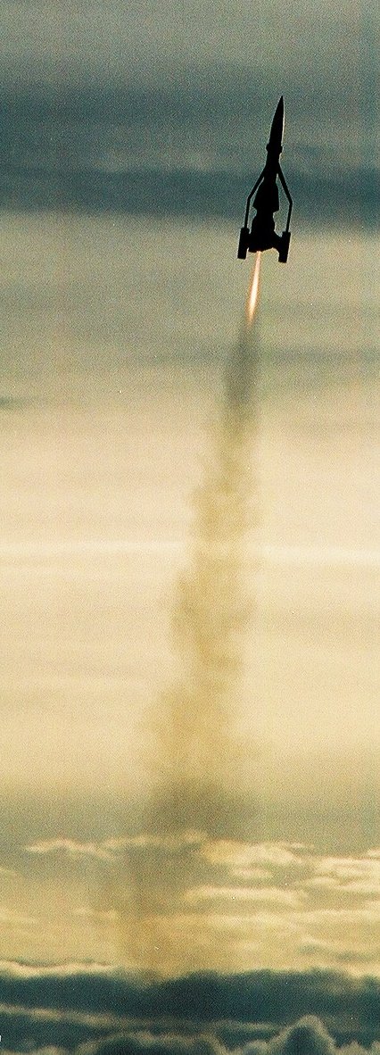
Launch: Copper Knobs
Motor: H153
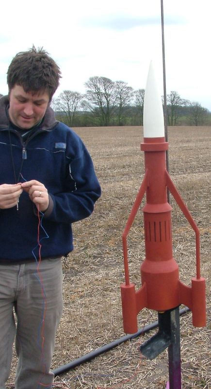
This was the big test. I had tried to develop a good model in RockSim, but with a rocket this untypical, you can never tell how accurate it will be until you actually fly. There was a fair bit of finishing off to do. The recovery harness needed putting together. weight adding to the nose, and also attaching the nose. I hadn't really thought through the consequences of adding so much nose weight, 600g in all. This made the normal nose cone attachment point very unsuitable. So I tied the strap to a piece of threaded rod, pushed it through the small hole I made to pour in the rocket caviar, added a pour of epoxy and pulled it tight.
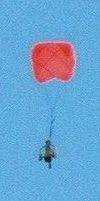
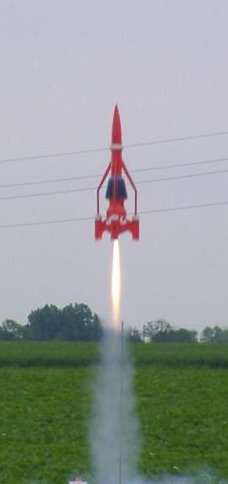
The flight went well, quite straight even in the reasonably stiff breeze, the ejection was just a little after apogee. Descent was too fast though, and the combination of the descent rate and lateral speed caused two of the fins to pop off. Everything came apart where it was joined though, so it went back together easily enough.

Mike Crewe's video [~3.2Mb avi format]
Mike Crewe's video [~3.7Mb mpeg format]
Launch: EARS
Motor: H143
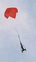
Once back together, I wanted to try flying with a bigger parachute. Unfortunately I read the wrong number from my RockSim print out - "time to apogee" instead of "ideal delay" and so ejection was approximately 1.8 seconds after apogee. TB3 had arced over and was pointing straight down by then, though the parachute deployed OK, and landing was much softer than the first flight.


Damian Burrin's video [~1.5Mb mpeg format]
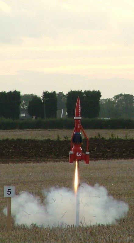
Launch: EARS
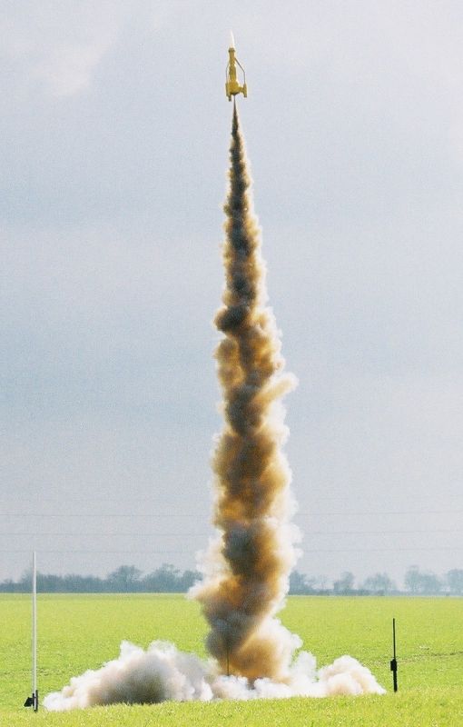
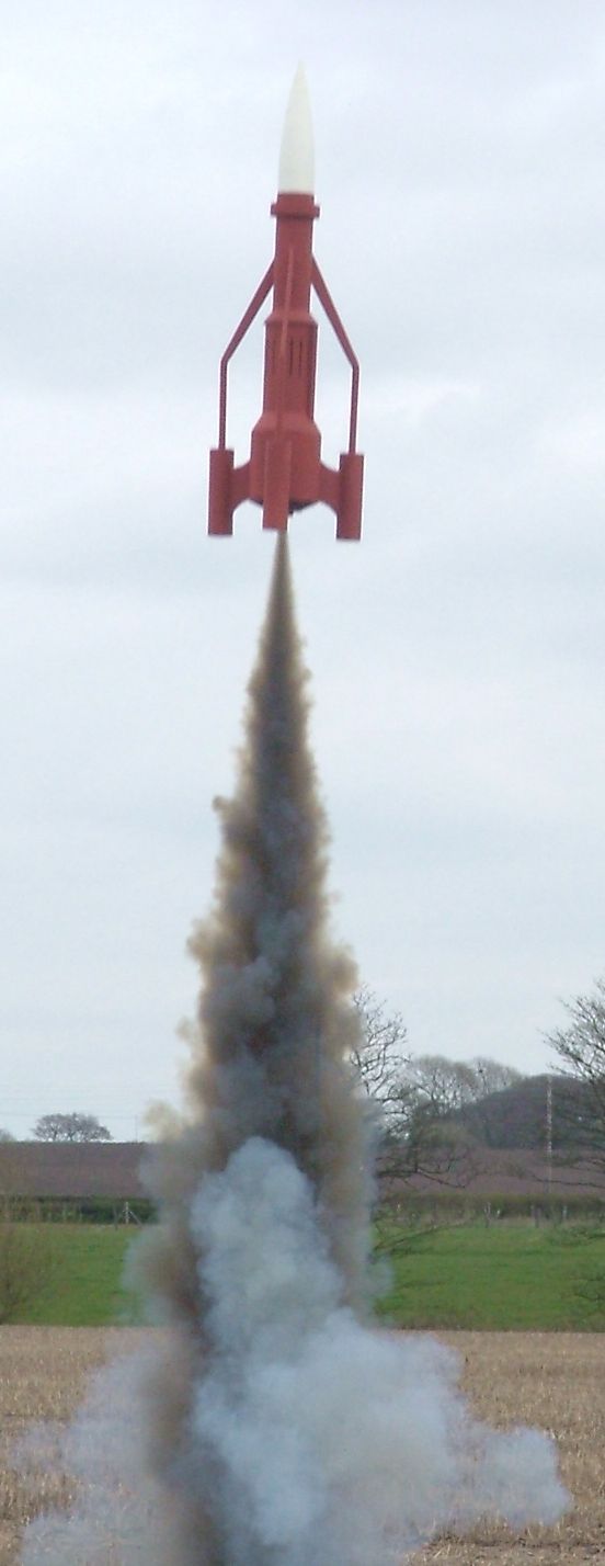
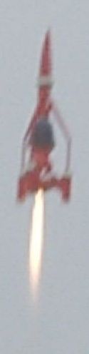
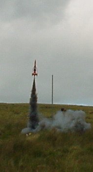
Motor: I212
It was a long drive to Cambridgeshire to fly just once. So I flew it again. This time on the I212. This was the best flight yet. A very straight boost, tons of smoke and ejection precisely at apogee. Unfortunately, there was a little damage on landing. One of the "flying buttresses" came detached. It would have been easy to fix, but I noticed that some of the other fin attachments were a bit wobbly, which was when I decided that a rethink was necessary.

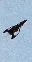
Launch: WRS
Motor: H143
Another flight on an H143. This flight was after the rebuild. Very nice flight, from my viewing point on the ground, the silhouette from below clearly showed all three fin pods. Unfortunately someone else was driving my camera. I'm now starting to wish I had made provision for effects motors in the pods. Anyway, the strengthening exercise was a success, as there was no damage whatsoever after this flight.
Launch: BigEARS
Motor: I205
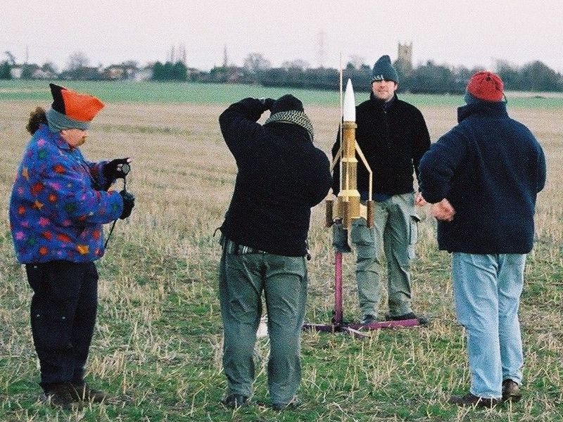
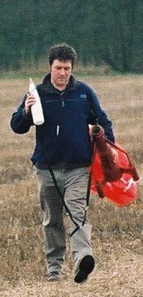
Not very nice weather at this launch. When the wind and rain finally cleared we were left with a ceiling of about 1500'. Just enough for a flight on an I205. There was a lot of interest in the flight, not only were people interested in TB3, but it was also one of very few HPR flights made that day. I don't know who's idea it was to play the Thunderbird's theme over the PA, but many thanks to Mike Roberts for coming out with a PRM. I couldn't actually hear it until then! I've not yet seen a video of my "supermarionation walk", but it appeared to amuse the spectators.
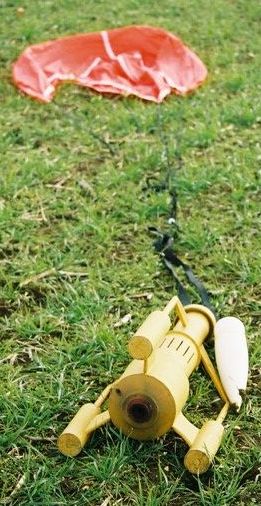
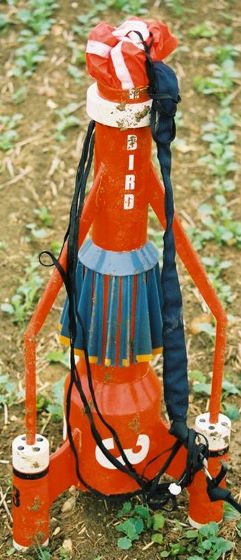
The launch and boost were very good, though perhaps not as straight as previous flights. The delay was a little long, perhaps due to additional weight of paint, and it arced over before appearing to deploy. Partially deploy, anyway. The chute stayed in the end of the body tube and refused to come out. The problem was later diagnosed to be the length of the chute shroud lines compared to the length of the shock cord. Basically the shock cord could extend to it's full extent without pulling out the parachute. A very obvious error in retrospect. I must have just been lucky, on the previous flights, that the parachute was completely pushed out.
Considering it fell from 1500', there was surprisingly little damage. The damage is mainly restricted to the fin roots & buttresses. One of the buttresses has detached from the corresponding pillar, but will be easy to fix. The forward section appears to have had a bit of a crimp, but it doesn't look deformed, which is a bit odd. There is also a little damage around the transition between the aft and centre sections, but it's cosmetic rather than structural. One of the main fin roots has been partially pulled out, and will need to be reseated and re filleted. So, in summary, lots of little things to fix, all of which will be tricky without completely ruining the paint job.


Paul Shackleton's video [~1Mb wmv format]
Steve Woolhead's video [~0.5Mb wmv format]
Steve Woolhead's video [~13Mb mpeg format]
Chris P. Brown's video [~3.8Mb mpeg format]
Launch: UKRA 2004
Motor: I205
After the Big EARS launch, there were quite a lot of repairs to do, but none of it was really serious. Some of the fin fillets were dremmeled out and redone, and the paint needed touching up in several places. I also made a length of coupler and fitted it inside the forward body tube, to strengthen it. It was very awkward to touch up the paintwork with some tricky masking being required. Consequently, some areas have suffered from overspray, but it still looks good from a distance!
Bit of a surprise at this launch, the Dutch guys from Tripoli The Netherlands turned up with two Thunderbird Threes of their own, one smaller and the other larger. In many ways, their TB3s were better than mine, the noscones were of the correct aspect ratio, and the the pods were curved. I tried to talk them into a drag race, but they weren't too interested. They did kindly lend me an igniter though, after I left mine back at the prep hut.
The flight on the I205 went well, with deployment at apogee and safe landing ate the edge of the field we were launching from.


Dave Hart's video [~16Mb mpeg format]
Launch: UKRA 2004
Motor: I284
I wasn't intending to fly on the Sunday, but I was tempted into it by the thought of cramming in the four grain I285. It was a great flight, though a little damage was sustained to the forward "radiator cap" transition, when it landed on a rock. Given the protection granted to this area by the "buttresses" it was very unlucky! Although cosmetically irksome, teh damage is in no way stuctural, and so I'm not even tempted to think about fixinig at present.


Launch: International Rocket Week 2004
Motor: I212
This flight took place at a new HPR flying for the IRW, Fairlie Moor. It's a nice site. There's a public road running throught the centre of it, but very little traffic. Best of all is the proper car park. The main problems were the highland cattle, and the possibility of rockets coming down in a lake due to the wind, but it was one of the best days weather-wise and we made the most of it!
Due to the nature of the flying windows (all HPR flying at the IRW is done in conjunction with Glasgow ATC) and other rocketeers faffing with rockets on the pad _during_ a flight window, I had very little time in which to complete my prep. Consequently, the nose cone was a little loose, and seperated at motor burnout, giving a text book example of boosted dart theory, as well as a graphic illustration of why you should never rush your launch prep!
It was still a cool flight though, there was no damage either when the parachute deployed, or on landing, and I was very pleased to have flown TB3 at the IRW, my favourite flying event of the launch calendar.


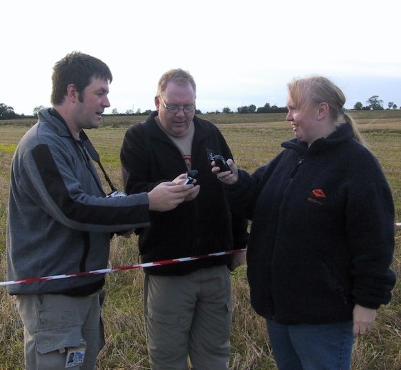
Launch: K-Lob 2004
Motor: H153
Only managed to get one day at K-Lob, and the weather wasn't idea - pretty windy. I did managed to get some flights in towards the end of the day though. Colin got some excellent take off pics. If you're wondering what the three loons with the phones are doing, we're listening to the Thunderbirds theme in "poor man's surround sound" on our Sony Ericsson T610s - surprisingly effective! I remember it as a fairly uneventfull flight, but Chris' video makes it look as though the deployment was very late!


Chris P. Brown's video [~2.1Mb mpeg format]
Picture & Video Credits
Many thanks for all those who allowed their pictures and videos to be used in this article. If this comes as a surprise to any of you, I'll apologise now! I did try to contact you with the most recent email address I had, but received no reply. If you do not wish your pictures and/or video to be used, let me know and I'll remove them as soon as possible.
All pictures are copyright the photographer. Thank you to: Chris P. Brown, Damian Burrin, Mike Crewe, Pete Davy, Dave Hart, Ben Jarvis, Paul Lavin, Niall Oswald, Colin Rowe, Paul Shackleton, Pete Waddington & Dan Westley. For individual attribution, see the filename. Unattributed files are copyright the author.